INFINITE-HIL X1 · 3-DOF UAV test rig - UAV test platform
Continuous 360° motion on three axes. A UAV test and simulation platform.
X1 is a modular HIL platform for evaluating real UAV hardware under controlled roll, pitch and yaw motion. Servo actuation, absolute encoder feedback and multi-sensor instrumentation are combined in one architecture to support control development, system identification and production quality control.
Vehicle geometry, mass and inertia, motion profile, instrumentation requirements and budget are assessed together to define the configuration, from fixture to control software.
Motion, measurement and control in one architecture.
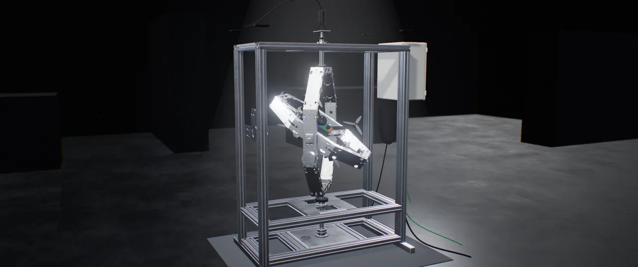
X1’s concentric rotary structure combines physical attitude motion with angular reference, sensor response and control data. The architecture is adapted to the product under test and its measurement objectives.
Continuous three-axis motion
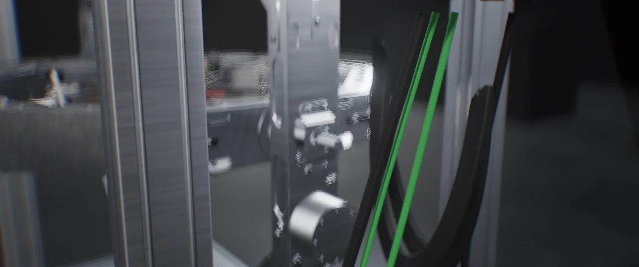
Slip-ring transfer on roll, pitch and yaw carries power and signals through the rotary structure without cable-wrap travel limits. Motion profiles are defined around vehicle geometry, inertia and the selected actuation configuration.
Absolute angular feedback
A 21-bit multi-turn absolute encoder on each axis provides angular reference for motion monitoring and closed-loop control. IMU and application-specific force/torque measurements support analysis across multiple data sources.
Product-specific mechanical integration
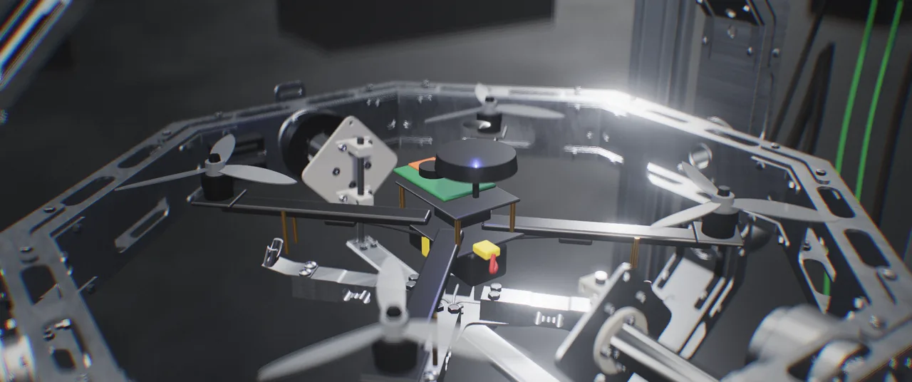
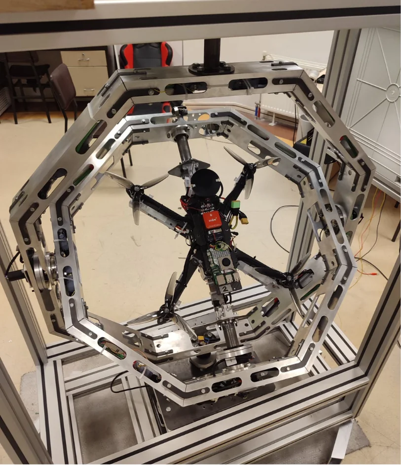
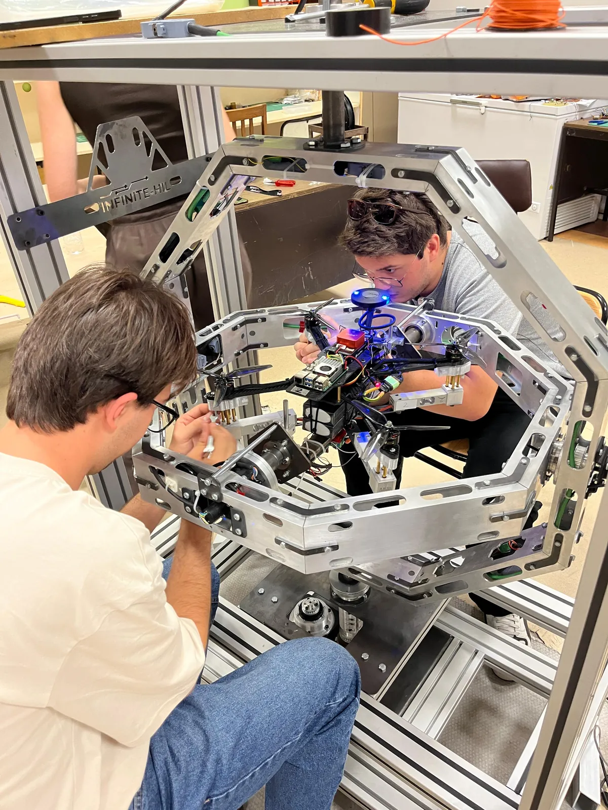
The vehicle is secured through a fixture matched to the roll-axis mounting interface. Centre of mass, clearances and test loads are considered together; fixtures may be customer-supplied or engineered by INFINITE-HIL.
Mechanics
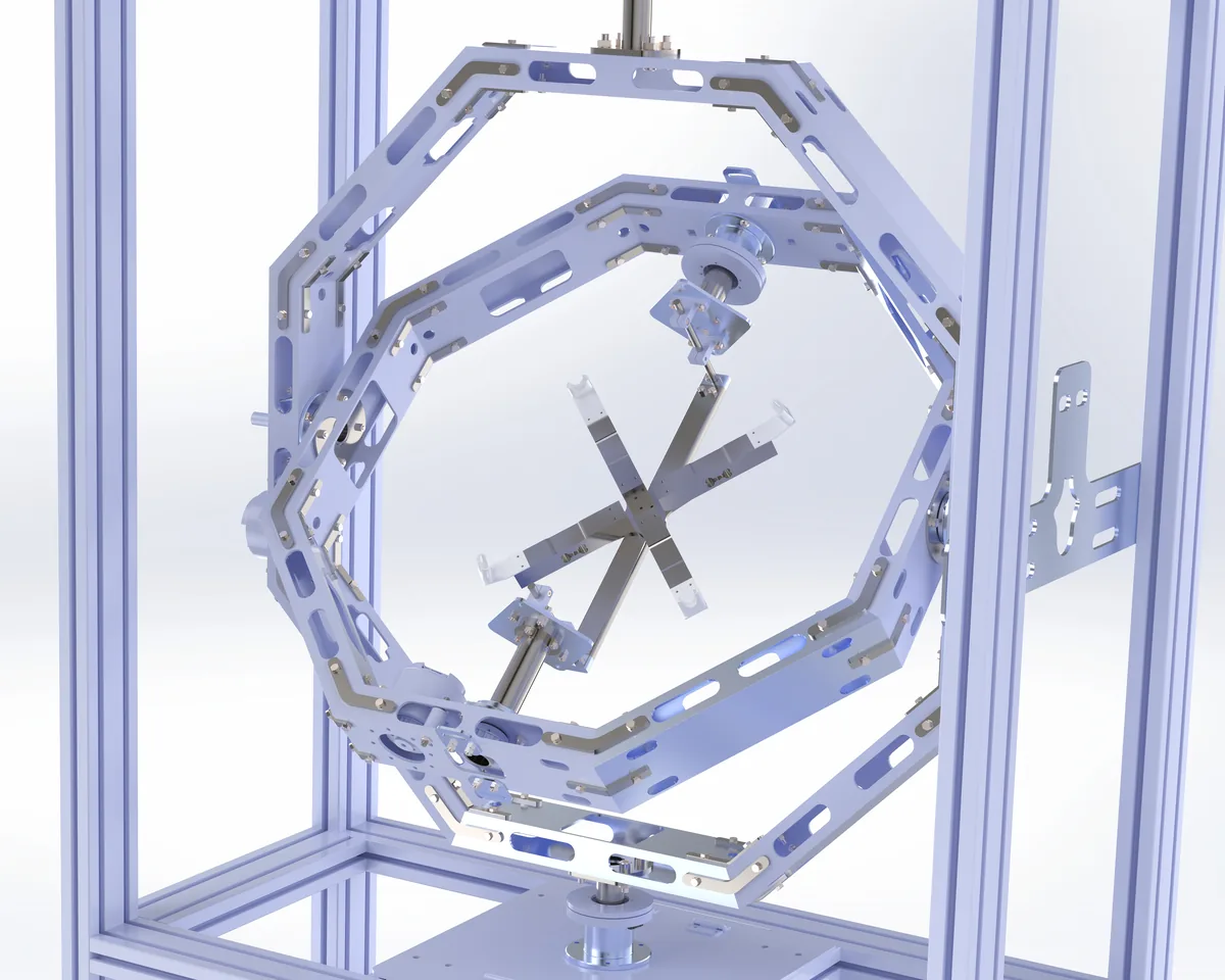
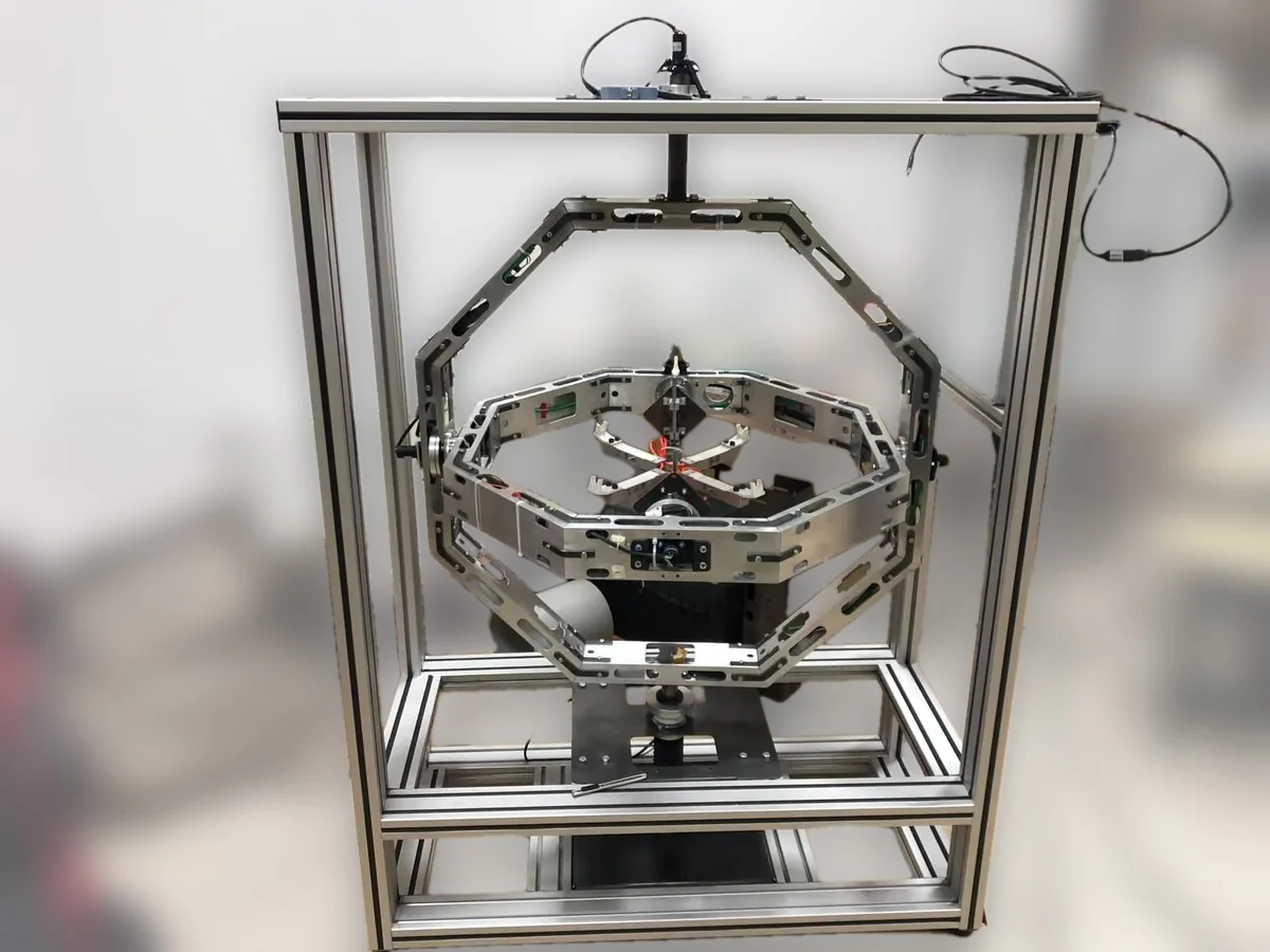
Three axes, one intersection point
Yaw
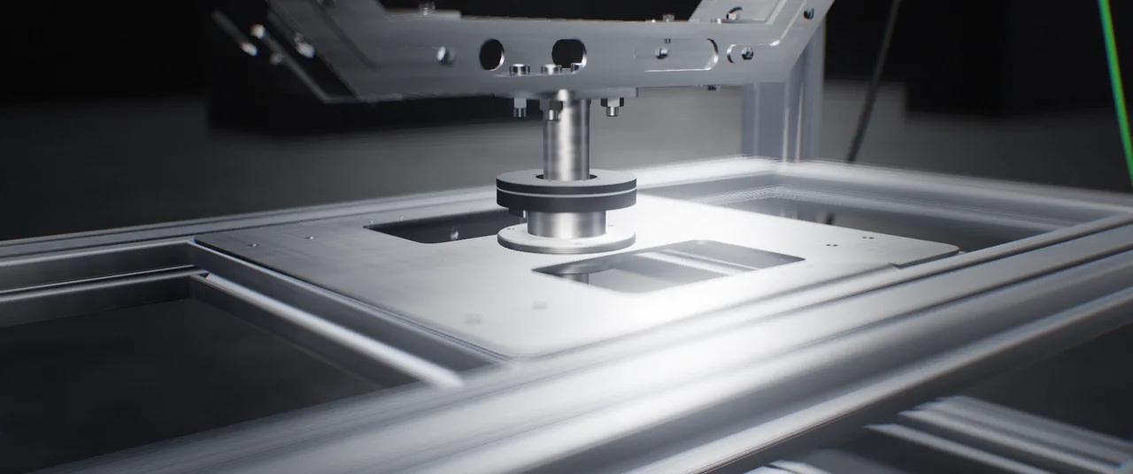
Yaw · outer octagonal ring
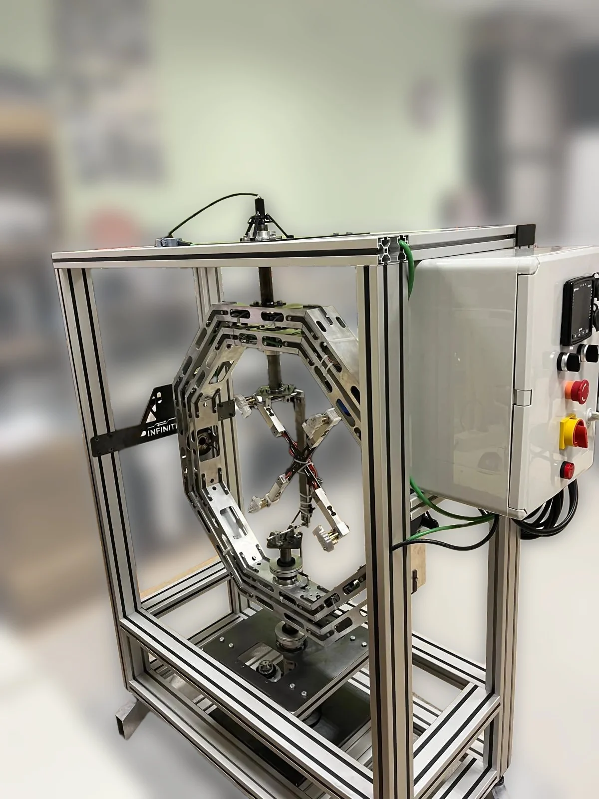
Driven from the steel base plate, guided by a top bearing on a black mast. A slip ring on top carries power and signals across the rotating joint.
Pitch
Pitch · inner ring
Pivots on two opposite corners of the outer ring, with the drive and pulley on one side and bearings on both. Laser-cut, bent aluminium channel segments keep it light and stiff.
Roll
Roll · vehicle fixture
Spans the inner ring along 30 mm shafts. The vehicle is secured through a fixture matched to the roll-axis mounting interface, with its centre of mass aligned to the centre of rotation.
Interactive 3D
Explore the X1 in real time
X1 simulation. Drag to rotate and use the sliders to control each axis.
Loading the X1 CAD model
Drag to orbit · scroll or pinch to zoom
Operating approaches
An operating approach matched to your test objectives.
Programmed orientation sequences, closed-loop scenarios and free simulation are addressed within the same product architecture. The selected mode is defined together with the motion and measurement configuration.
Programmed motion and orientation testing
Use defined angular positions and motion sequences for sensor, calibration and unit-comparison studies. Profiles, records and evaluation steps are configured around your test plan.
HIL and disturbance-torque scenarios
Evaluate the control system using real hardware feedback and model-based test inputs. Closed-loop disturbance-torque injection supports analysis of control response to application-defined dynamic effects.
Free simulation
Use the free-operation approach to examine the rotational response of the system under test. Mechanical behaviour and control settings for this mode are defined around the vehicle, motion range and measurement objectives.
Laboratory and software
Designed for dependable laboratory testing.
Control infrastructure
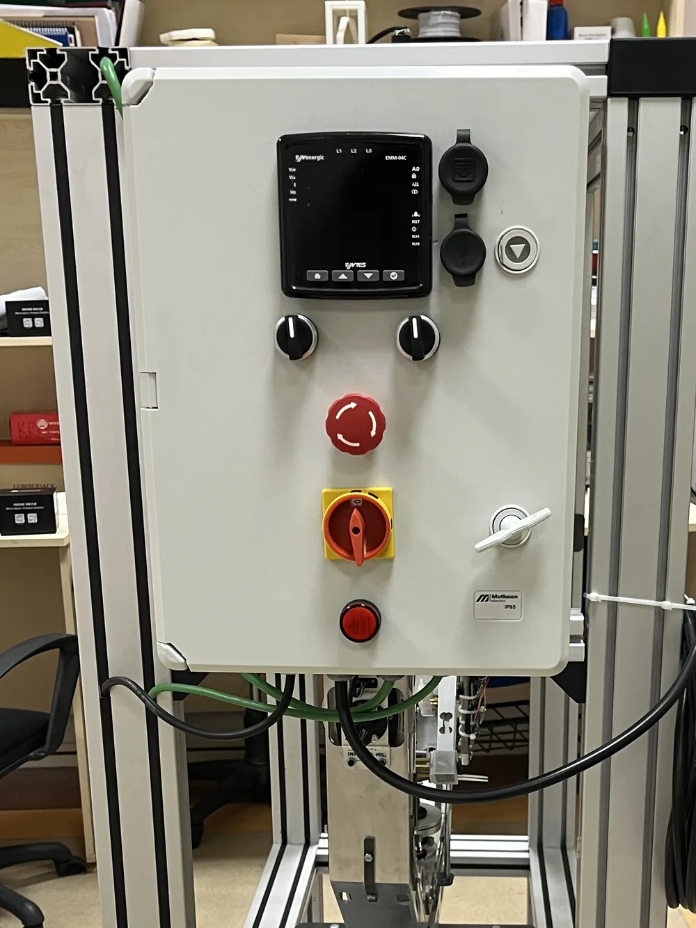
Manage servo motion control, system connections and operator access through the central cabinet. Test setup and operating limits are defined together with the selected hardware and application requirements.
Coordinated measurement
Evaluate angular reference, IMU and project-specific force/torque data together. Measurement points and sensor scope are configured around the physical behaviour under investigation.
Real-time monitoring
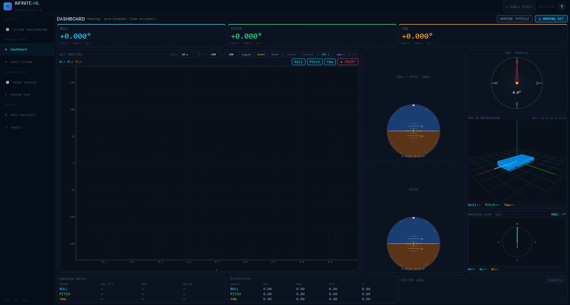
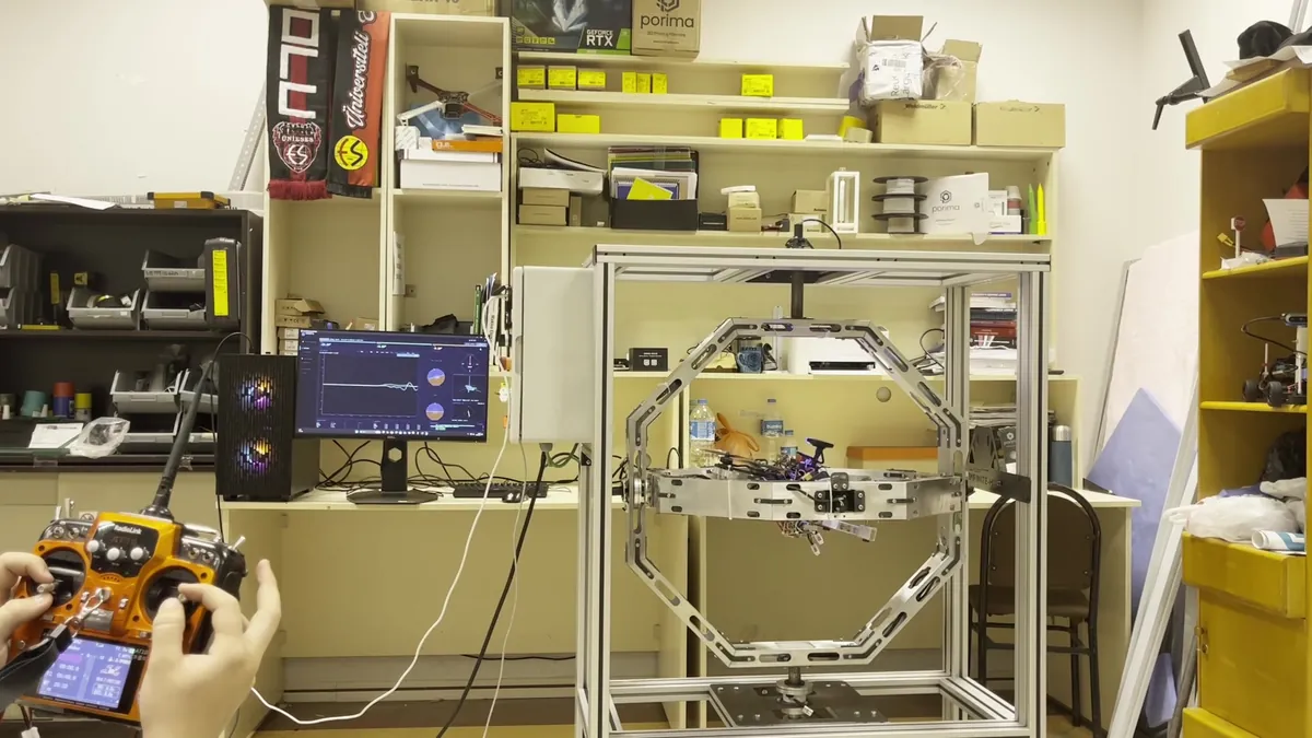
Follow attitude visualisation, compass, motion and calibration panels, and telemetry charts in a shared interface. Examine system behaviour and recorded data within the test workflow.
Model and software integration
Connect the MATLAB/Simulink Embedded Coder PIL/HIL workflow and ROS 2/Gazebo digital-twin interface to your development process. Data and control paths are configured for the existing infrastructure.
Control cabinet · main switch and emergency stopINFINITE-HIL Control Suite · monitoring interface
Specifications
X1 technical specifications
Mechanical motion, instrumentation and software integration are configured as one system. The reference values below provide a starting point for defining your project-specific technical scope.
X1 technical specifications
Feature
Reference configuration
Rotational motion
3 axes: roll, pitch and yaw; continuous 360° rotation on each axis.
Angular measurement
21-bit multi-turn absolute encoders on every axis.
Weight capacity
Up to 25 kg in a suitable configuration; assessed with inertia, centre of mass and motion profile.
DUT envelope
Up to 600 mm rotor-to-rotor in the reference mounting arrangement; scalable for custom vehicles.
Inertial sensing
9-DOF IMU: accelerometer, gyroscope and magnetometer.
Force and torque
Multi-channel acquisition at application-specific measurement points.
Control and interfaces
Closed-loop servo control; CAN, Ethernet/UDP telemetry and serial communication over USB.
Programmed orientation sequences, free simulation and autonomous disturbance-torque injection.
Actuation
BLDC servo actuators with planetary reduction; axis torque selected for the application.
Controller and host
32-bit ARM Cortex-M4; Windows or Linux monitoring and control application.
Reference envelope
1040 × 520 × 1300 mm (width × length × height); custom configurations may differ.
Power input
Single-phase 220 VAC, 50 Hz, supplied through the control cabinet.
Operating temperature
Datasheet reference range: 0–70 °C; included in application-specific configuration assessment.
Values describe the X1 reference configuration. Mechanical envelope, fixture, weight capacity, axis torque, instrumentation and software scope are defined around your project requirements and budget.
The manufactured system
System images
INFINITE-HIL X1 front view with the inner ring levelINFINITE-HIL X1 side view, control cabinet viewUAV mounted to the roll-axis fixture inside the X1 ringsEngineers mounting the test UAV in the X1RC transmitter, Control Suite monitor and X1 during a HIL test
Your project
Let’s configure X1 for your test requirements.
Share your vehicle geometry, target motion and measurement needs so we can assess fixture, actuation, instrumentation and software scope alongside your budget.