What “3-DOF” means for a drone test rig
A rigid body in space has six degrees of freedom: three translations (x, y, z) and three rotations (roll, pitch, yaw). A 3-DOF UAV test rig fixes the translations and leaves the three rotations free — exactly the motions an attitude controller is responsible for.
That makes a 3-DOF rig the natural place to tune and verify attitude control: the vehicle can pitch, roll and turn as in flight, but it cannot fly away, fall or hit anything.
Types of drone test rigs
- Thrust stands measure motor and propeller thrust and torque. Essential for propulsion, but static — no attitude motion.
- Single- and two-axis rigs (a drone on a rod or hinge) are cheap and useful for a first PID loop, but couple axes artificially and miss yaw or cross-coupling.
- Ball-joint and tether rigs allow 3 rotations, but only within ±20–40° and with friction that changes with load.
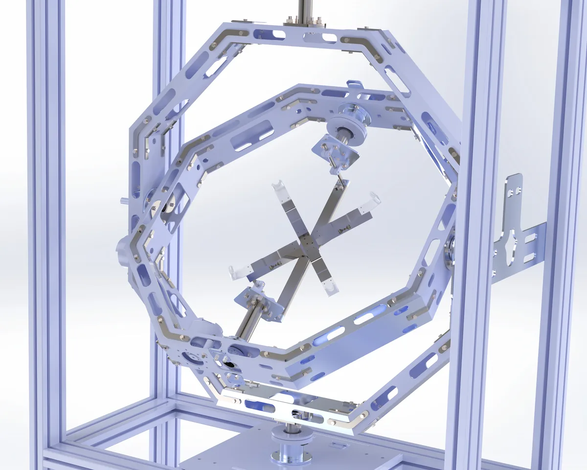
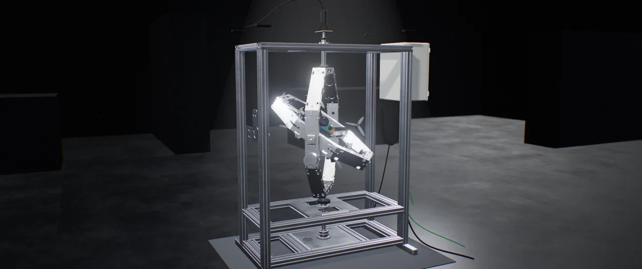
- Nested gimbal rigs (gyroscope-style rings) give all three rotations through the vehicle centre — with slip rings, continuously through 360°. This is the X1 architecture.
- Motion simulators and rate tables are precise tools for inertial sensors and avionics, but are built to move sensors and boxes, not to carry a complete UAV — and are usually expensive and export-controlled.
What to look for in a 3-DOF test rig
- Centre of rotation at the vehicle’s centre of mass. Otherwise gravity adds a torque the vehicle never feels in flight.
- Continuous rotation. Hard stops and cable wind-up limit your tests to small angles. Slip rings remove both.
- Low and known friction and inertia. Ring inertia and bearing friction change the dynamics; they must be small, measured or actively compensated.
- A measured reference. Encoders on every axis give you the ground truth to compare against the vehicle’s own attitude estimate.
- Data synchronisation. Commanded and measured signals need a common time base — milliseconds matter.
- Safety. An emergency stop, guarding and a restrained vehicle, especially if propellers will ever spin.
| Criterion | Flight test | SIL simulation | Thrust stand | Ball-joint / tether rig | INFINITE-HIL X1 |
|---|---|---|---|---|---|
| Real flight controller and sensors | MetReal hardware | Not metModel only | Partly / depends on configurationDepends on setup | MetHardware can be mounted | MetVehicle / board / sensors |
| Physical attitude motion on three axes | MetWithin vehicle capability | Not metNo physical motion | Partly / depends on configurationFixed / limited axes | Partly / depends on configurationLimited angles | MetControlled roll / pitch / yaw |
| Continuous 360° rotation | Partly / depends on configurationDepends on manoeuvre | MetVirtual rotation | Not metNot a core function | Partly / depends on configurationMechanical / cable limits | MetSlip ring on every axis |
| Risk to the vehicle | Not metFlight / crash risk | MetNo physical test vehicle | Partly / depends on configurationRotating-part hazard | Partly / depends on configurationDepends on restraint | MetControlled test on a fixture |
| Repeatable, scripted profiles | Partly / depends on configurationWeather / pilot / site effects | MetSame model / inputs | Partly / depends on configurationLimited command sequences | Partly / depends on configurationDepends on actuation / control | MetProgrammed motion / test sequences |
| Measured attitude reference | Partly / depends on configurationSensors / extra reference | MetNumerical reference | Partly / depends on configurationNeeds extra measurement | Partly / depends on configurationExtra instrumentation | MetAbsolute encoder / IMU |
| Suitability for production QC | Partly / depends on configurationField / operational overhead | Partly / depends on configurationNo physical verification | Partly / depends on configurationMotor / thrust subsystem | Partly / depends on configurationMeasurement / automation | MetUnit-level data / acceptance |
Tick: met · cross: not met · dash: partly or configuration-dependent. In the risk row a tick marks the more controlled condition, not zero risk. In SIL, rotation and reference are virtual.
A word on gimbal lock
Any nested three-axis gimbal has a singular configuration when the middle axis reaches ±90°: two axes line up and one rotation direction is momentarily lost. It is a property of the geometry, not a defect. Good test profiles and motion controllers account for it, and for most attitude-control testing it is avoided by design.
From test rig to hardware-in-the-loop
A passive rig lets the vehicle move itself. A motor-driven 3-DOF platform can also impose motion: scripted profiles for sensor checks and QC, or the attitude computed by a vehicle model from the flight controller’s outputs. That second case is hardware-in-the-loop testing — the real flight controller and sensors in a closed loop with simulation.
Three-axis testing and validation with X1
INFINITE-HIL X1 is a three-axis HIL testing and simulation platform for evaluating UAV systems under controlled laboratory conditions. By combining yaw, pitch and roll motion in one setup, it supports the assessment of flight control hardware and sensor response under physical motion.
The mechanical structure, drive system and software integration can be configured around your UAV, test scenarios and budget. Motion performance and measurement capabilities depend on the selected configuration.
- Three-axis motionControlled attitude motion across yaw, pitch and roll axes, with repeatable test scenarios.
- UAV-specific mountingMounting tailored to the test setup through a roll-axis fixture designed for the UAV structure.
- Real-time monitoringCombined monitoring of axis and sensor data through INFINITE-HIL Control Suite.
- Project-specific configurationMechanical, hardware and software options tailored to the test scope.