More efficient development
Evaluate control parameters, sensor-processing approaches and software updates against defined test profiles. Repeat the same scenario to compare changes and build stronger engineering evidence before field testing.
INFINITE-HIL · Test & Simulation Systems
Build engineering decisions on measurable data.
INFINITE-HIL designs and builds modular HIL platforms, custom test machines and simulation infrastructure for developing and validating control systems, avionics and electromechanical products. From mechanical design to instrumentation and control software, each solution is configured around your product, test objectives, project scope and budget.
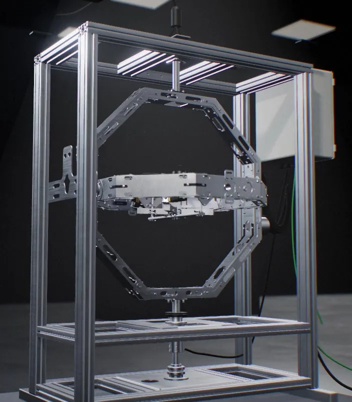
INFINITE-HIL X1 · 3-axis HIL test platform
Why HIL
Mathematical models accelerate development; physical hardware reveals interactions between sensors, mounting, timing and control. HIL brings the two into one test workflow, supporting design decisions with repeatable measurements.
Evaluate control parameters, sensor-processing approaches and software updates against defined test profiles. Repeat the same scenario to compare changes and build stronger engineering evidence before field testing.
Test the flight controller, sensors and connections under physical motion. Compare encoder reference and sensor data to investigate integration effects that may not appear in a software-only model.
Establish defined motion sequences, consistent measurement and recorded results for R&D and quality control. Configure the test scope around product requirements to compare revisions and individual units.
INFINITE-HIL X1
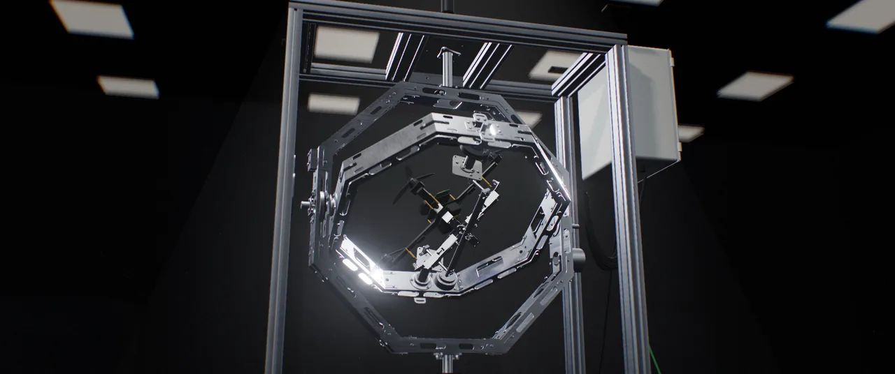
INFINITE-HIL X1 is a modular platform that combines controlled roll, pitch and yaw motion of real UAV hardware with measurement and simulation infrastructure. Continuous rotation, absolute angular feedback and project-specific instrumentation support attitude-control development, system identification and quality-control workflows.
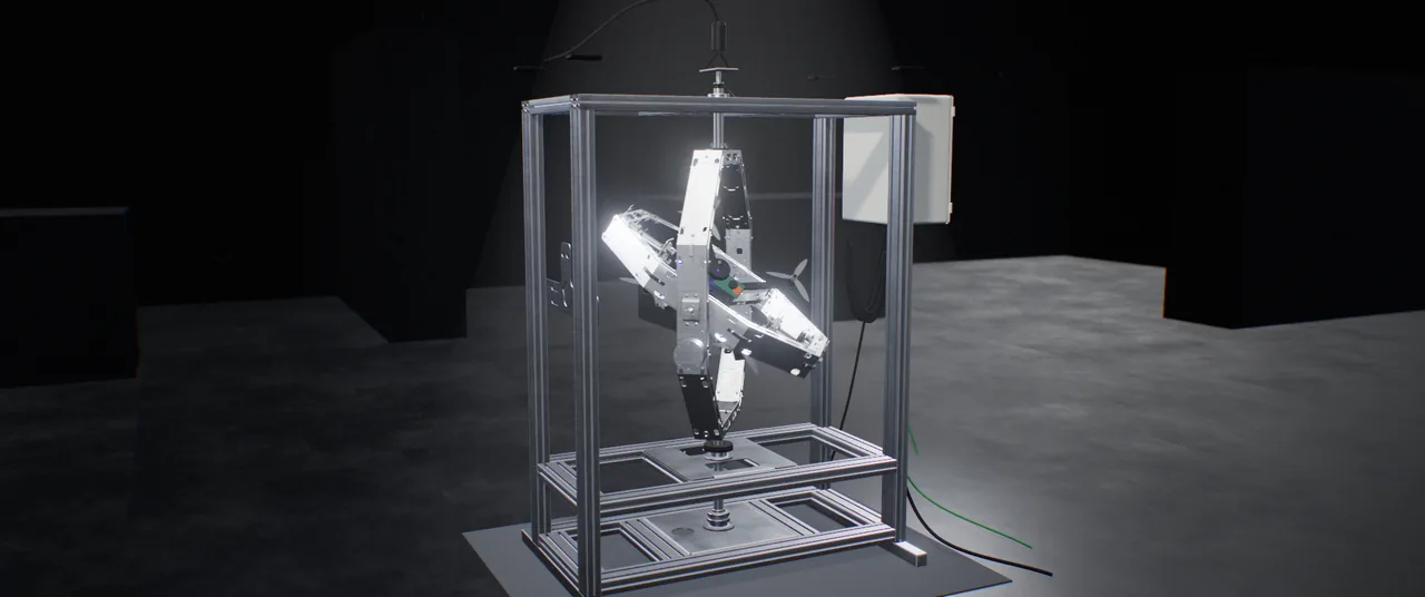
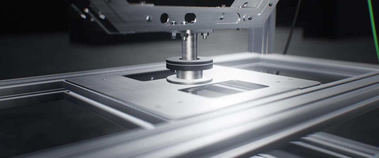
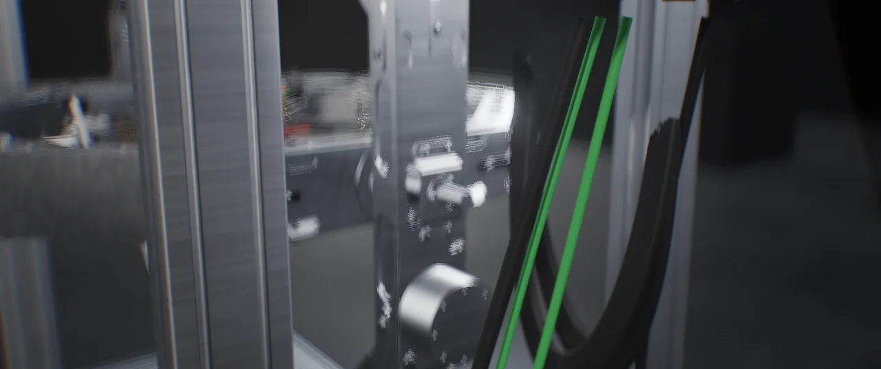
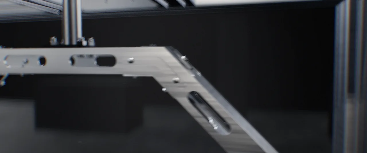
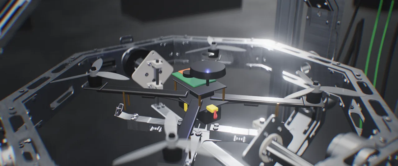
The concentric structure produces attitude motion around a shared centre; fixture placement is configured for the vehicle geometry and centre of mass.
Use continuous yaw rotation to examine orientation changes, magnetometer behaviour and control response in defined scenarios.
YawApply pitch motion profiles to compare sensor feedback and control behaviour at different orientations.
PitchMonitor physical roll motion alongside angular reference and vehicle telemetry.
RollCoordinate the axes to examine control and sensor behaviour under motion sequences matched to your test objectives.
The vehicle is secured to the roll-axis mounting interface through a fixture designed for its geometry and test loads.
Browser demo
Control the axes, change test scenarios and view the illustrative system response through the live charts.
Drag the sticks · keyboard WASD + QE · or connect your RC transmitter (USB joystick mode)
Interactive X1 simulation · Illustrative system response
Test sessions with our users
Explore platform motion, pilot inputs and control software across test sessions. These examples show how the test infrastructure is adapted to physical vehicles and application scenarios.
Product film · 1:00
Discover X1’s motion architecture, vehicle integration and measurement approach in the product film.
Applications
Custom machine, test and simulation solutions for UAV, aerospace and other industries, tailored to requirements and budget.
Evaluate control parameters, sensor feedback and flight-controller integration on physical hardware. Compare software revisions under defined motion profiles.
HIL testingBuild repeatable test sequences for assessing sensor and attitude response on individual units. Configure data records, automation and acceptance criteria for your production process.
UAV QC test stationAddress requirements beyond a standard rig through coordinated mechanical design, custom machine manufacturing, instrumentation, control and simulation. Define the solution scope around your product and budget.
Discuss your projectSupport control, sensor-fusion and system-identification studies with measurable physical experiments. Evaluate models and algorithms under shared test conditions.
Research applicationsComparison
Flight testing, software simulation and physical rigs serve different needs. X1 brings real hardware, controlled three-axis motion and measurement into one laboratory workflow.
| Criterion | Flight test | SIL simulation | Thrust stand | Ball-joint / tether rig | INFINITE-HIL X1 |
|---|---|---|---|---|---|
| Real flight controller and sensors | MetReal hardware | Not metModel only | Partly / depends on configurationDepends on setup | MetHardware can be mounted | MetVehicle / board / sensors |
| Physical attitude motion on three axes | MetWithin vehicle capability | Not metNo physical motion | Partly / depends on configurationFixed / limited axes | Partly / depends on configurationLimited angles | MetControlled roll / pitch / yaw |
| Continuous 360° rotation | Partly / depends on configurationDepends on manoeuvre | MetVirtual rotation | Not metNot a core function | Partly / depends on configurationMechanical / cable limits | MetSlip ring on every axis |
| Risk to the vehicle | Not metFlight / crash risk | MetNo physical test vehicle | Partly / depends on configurationRotating-part hazard | Partly / depends on configurationDepends on restraint | MetControlled test on a fixture |
| Repeatable, scripted profiles | Partly / depends on configurationWeather / pilot / site effects | MetSame model / inputs | Partly / depends on configurationLimited command sequences | Partly / depends on configurationDepends on actuation / control | MetProgrammed motion / test sequences |
| Measured attitude reference | Partly / depends on configurationSensors / extra reference | MetNumerical reference | Partly / depends on configurationNeeds extra measurement | Partly / depends on configurationExtra instrumentation | MetAbsolute encoder / IMU |
| Suitability for production QC | Partly / depends on configurationField / operational overhead | Partly / depends on configurationNo physical verification | Partly / depends on configurationMotor / thrust subsystem | Partly / depends on configurationMeasurement / automation | MetUnit-level data / acceptance |
Tick: met · cross: not met · dash: partly or configuration-dependent. In the risk row a tick marks the more controlled condition, not zero risk. In SIL, rotation and reference are virtual.
Technical features
X1 combines continuous three-axis motion with high-resolution angular feedback and configurable instrumentation. The values below describe the reference configuration; vehicle dimensions, load, motion profile and budget are assessed together to define the appropriate system scope.
Values describe the X1 reference configuration. Mechanical envelope, fixture, weight capacity, axis torque, instrumentation and software scope are defined around your project requirements and budget.
FAQ
It is laboratory infrastructure for evaluating real control hardware, sensors and physical rotational motion in one test workflow. X1 produces roll, pitch and yaw motion while measurement and simulation layers support control-response analysis.
Software simulation evaluates control and environment models numerically. HIL includes real control hardware in the loop; X1 also provides physical attitude motion. Sensor and integration effects can be assessed within that physical scope.
Fixture, mechanical envelope, axis torque and instrumentation are selected for vehicle geometry, mass, inertia and test profile. The datasheet specifies up to 600 mm rotor-to-rotor for the reference mounting arrangement and up to 25 kg in a suitable configuration; these two figures alone do not establish compatibility.
X1 can be configured for defined orientation sequences, sensor-data records and unit-level evaluation. Automation level, data interfaces and acceptance logic are defined around the customer’s production and quality-assurance processes.
Slip-ring power and signal transfer enables continuous 360° rotation on each rotational axis without cable-wrap travel limits. Combined-axis motion remains dependent on geometry, motion profile and the selected configuration.
Yes. Alongside UAV applications, we design custom machines, test systems and simulation infrastructure for different industries. Mechanical, electronic, sensing, control and software scope is defined around test objectives, product requirements and budget.
Your project
Tell us about your product, the behaviour you need to validate and your project objectives. Together, we can define a solution that fits your requirements and budget, from mechanical design to measurement and software integration.