Control-parameter development
Compare the effect of PID and related control parameters on the physical system under defined orientation and motion profiles. Examine different settings within the same scenario.
Solution · Flight controller HIL testing
Test your flight controller, sensors and connections under controlled three-axis motion. INFINITE-HIL X1 combines physical attitude motion with measurement, control and simulation layers, bringing algorithm development, integration and validation workflows into the laboratory.
Definition
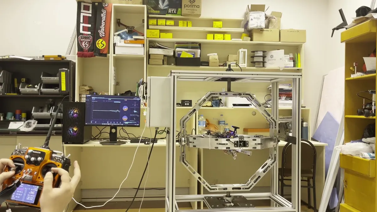
Hardware-in-the-Loop (HIL) is a test approach in which real control hardware interacts with a simulated system or environment in a closed loop. Hardware outputs influence the test model, while feedback from the model or physical rig is returned to the controller. This allows software behaviour to be evaluated together with real hardware and interfaces.
A three-axis motion platform also changes the physical orientation of the UAV. Its IMU and other attitude-related sensors experience real rotational motion, while additional dynamics required by the test are addressed through models and data interfaces. X1 combines this physical motion with measured angular reference and configurable test scenarios.
The test loop
What you can test
Typical flight-controller and autopilot test bench tasks, from PID tuning and IMU or sensor-fusion checks to regression testing.
Compare the effect of PID and related control parameters on the physical system under defined orientation and motion profiles. Examine different settings within the same scenario.
Evaluate IMU and magnetometer data alongside encoder reference. Investigate mounting orientation, offset and calibration effects within the measurement scope of your application.
Configure closed-loop scenarios with application-defined disturbance-torque inputs. Evaluate control response within the conditions represented by the selected model and physical motion.
Repeat the same test sequence following a hardware or software update. Track the effect of changes by comparing measurement and vehicle data under shared conditions.
Observe RC inputs, platform motion and vehicle response together. Include operator interaction in the laboratory test plan to evaluate control behaviour.
Examine the response of orientation-sensitive modules and stabilised sensors under controlled motion. Adapt mounting, data interfaces and measurement scope to the product requirements.
Comparison
Each approach produces a different type of evidence. An effective test plan combines early software development, evaluation with real hardware and field validation.
| Criterion | SIL | HIL with X1 | Flight test |
|---|---|---|---|
| Physical elements | Control software; vehicle and sensors are models. | Controller, sensors, connections and physical attitude motion. | Vehicle, environment and flight interactions. |
| Modelled / bounded scope | Vehicle dynamics, sensors and environment. | Scenario-dependent models; not all translation and aerodynamics are physical. | Operational conditions covered by the scenario and test site. |
| Risk and environment | No physical test vehicle required. | Fixture-mounted vehicle; motion and rotating parts require a defined setup. | Flight, environmental and operational risks are managed. |
| Repeatability | High for identical model and inputs. | Programmed profiles and measured angular reference. | Affected by weather, pilot, site and vehicle conditions. |
| Hardware effects | Does not directly measure physical sensor or wiring effects. | Mounting, offset, calibration, interface and timing effects can be studied. | Observed in operation; isolating causes may be harder. |
| Typical use | Algorithm development and model-based assessment. | Control tuning, integration, regression and configured QC. | Operational behaviour and final field validation. |
Integration
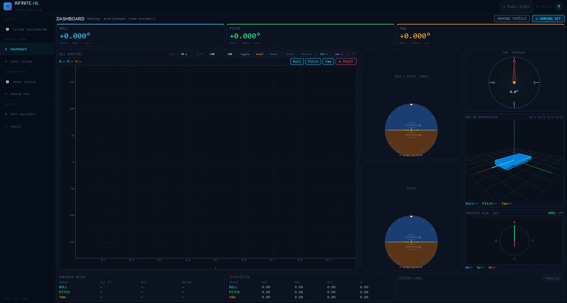
We consider your existing test ecosystem, from flight controller to analysis software. Physical motion, telemetry, model and recording interfaces are configured for your control architecture and validation objectives.
Comparison
Flight testing, software simulation and physical rigs serve different needs. X1 brings real hardware, controlled three-axis motion and measurement into one laboratory workflow.
| Criterion | Flight test | SIL simulation | Thrust stand | Ball-joint / tether rig | INFINITE-HIL X1 |
|---|---|---|---|---|---|
| Real flight controller and sensors | MetReal hardware | Not metModel only | Partly / depends on configurationDepends on setup | MetHardware can be mounted | MetVehicle / board / sensors |
| Physical attitude motion on three axes | MetWithin vehicle capability | Not metNo physical motion | Partly / depends on configurationFixed / limited axes | Partly / depends on configurationLimited angles | MetControlled roll / pitch / yaw |
| Continuous 360° rotation | Partly / depends on configurationDepends on manoeuvre | MetVirtual rotation | Not metNot a core function | Partly / depends on configurationMechanical / cable limits | MetSlip ring on every axis |
| Risk to the vehicle | Not metFlight / crash risk | MetNo physical test vehicle | Partly / depends on configurationRotating-part hazard | Partly / depends on configurationDepends on restraint | MetControlled test on a fixture |
| Repeatable, scripted profiles | Partly / depends on configurationWeather / pilot / site effects | MetSame model / inputs | Partly / depends on configurationLimited command sequences | Partly / depends on configurationDepends on actuation / control | MetProgrammed motion / test sequences |
| Measured attitude reference | Partly / depends on configurationSensors / extra reference | MetNumerical reference | Partly / depends on configurationNeeds extra measurement | Partly / depends on configurationExtra instrumentation | MetAbsolute encoder / IMU |
| Suitability for production QC | Partly / depends on configurationField / operational overhead | Partly / depends on configurationNo physical verification | Partly / depends on configurationMotor / thrust subsystem | Partly / depends on configurationMeasurement / automation | MetUnit-level data / acceptance |
Tick: met · cross: not met · dash: partly or configuration-dependent. In the risk row a tick marks the more controlled condition, not zero risk. In SIL, rotation and reference are virtual.
Your test loop
Share your flight-control architecture, model and measurement objectives so we can assess integration scope, mechanical configuration and budget together.